Dentures
PARALLELOMETERS.
TYPES AND DEVICES The use of the first devices for parallelometry dates back to the end of the 19th - beginning of the 20th century. During this period, various designs of bridges on screw-in and removable crowns, removable pin teeth, rings on crowns with spring protrusions, locking connections and other supports became widespread.
The manufacture of these structures required high precision and parallelism of the supporting parts, which, apparently, contributed to the creation of parallelometer devices. Already in the 20s of the 20th century, parallelometers appeared for bridge work by Sixt, Ney, and others, which were used to identify parallel areas on abutment teeth, accurately prepare proximal walls, adjust and parallel install inlays, locking fastenings and other support systems.
During the same period, support-retaining clasps for fixing removable bridges (Nesbett, Acker, etc.), as well as removable bridges with a clasp, simultaneously restoring several defects in the dentition, became widespread. This served as an impetus for further improvement of parallelometers and expansion of indications for their use.
the structure of parallelometers used in the manufacture of bridges and graphite pins. According to J. M. Ney [cit. according to E. Kennedy, 1942], the first specialist to evaluate the feasibility of using technical devices for accurately drawing the clasp line was the doctor Fortunati. In 1918
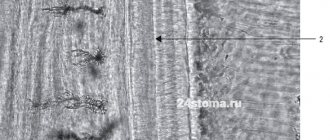
He demonstrated in Boston a method of using a parallelometer for bridge work, in which for the first time a hollow metal rod with a graphite core was installed, with which the equator of the abutment teeth was outlined. Subsequently, similar devices, called clasp markers, or clasp markers, found widespread use in the manufacture of clasp dentures (Fig. 2).
At the same time, devices for the manufacture of bridge structures were also gradually improved. Miniature intraoral devices have appeared that are attached to the teeth and ensure their preparation and the achievement of parallelism between the walls of the teeth, root canals and cavities for inlays. Some of them were later transformed into microparallelometers.
Interest in the issues of preliminary calculation of structures and measurement of parallelism of teeth has especially increased with the advent of steel alloys for casting dentures and their parts. The use of steels opened up prospects for mass and relatively inexpensive prosthetics. However, the use of these alloys for the manufacture of solid-cast clasp dentures was hampered for a long time due to the lack of effective sources for melting refractory steels and significant shrinkage of cast frames.
This was no less hampered by numerous failures associated with inaccurate manufacturing of structures. Thus, arbitrary modeling of clasp frames, without special measurements and calculations on the supporting teeth, inevitably required complex and time-consuming adjustment of castings both on the model and in the oral cavity.
Unreasonable selection and inaccurate placement of the supporting and holding elements of the clasp frames also led to numerous errors, which, however, were most often associated with shrinkage of the castings. The improvement of casting technology, the development of high-strength steel alloys and methods for reducing their shrinkage served as the basis for the analysis and revision of the reasons causing
Rice. 2. Scheme of the clasp device.
these errors and difficult fitting of solid frames. In turn, this contributed to the further improvement of parallelometers and the development of methods that allow preliminary calculations, as well as a thorough analysis and assessment of the remaining teeth on the jaw, taking into account their spatial movement and tilts, which increase non-parallelism. The development of the theory of parallelometry and the first scientifically based techniques is associated with research
B. Novak (1955), G. L, Roth (1942), J. M. Ney Company (1949, 1965).
Much credit for the further development of the theory and practice of parallelometry and the creation of original domestic parallelometers belongs to A. P. Grozovsky (1946), V. Yu. Kurlyandsky, V. D. Shorin and
A. A. Gremyakina (1962), E. I. Gavrilov, L. B. Malkov and M. A. Elgard (1966), G. P. Sosnin (1966, 1971, 1981), A. A. Doronin (1968), S. D. Schwartz (1968),
S. D. Schwartz and A. Ya-Tsodikovich (1968), V. A. Shcherbakov (1971), Ya-M-Lipovetsky and I. M. Lipovetsky (1971), V. V. Svirin (1972), E I. Gavrilov (1973), L. M. Perzashkevich, I. M. Strekalova, D. N. Lipshits and A. V. Ivanov (1974), V. I. Kulazhenko and S. S. Berezovsky (1975 ), N.V. Kalinina and V.V. Svirin (1976), V.N. Kopeikin, E.M. Lyubarsky, V.Yu. Kurlyandsky, S.M. Eidinov and I.V. Igonkin (1976) ,
V. N. Kopeikin (1977), V. P. Panchokha (1981), E. Ya. Vares (1979), V. Yu. Milikevich and Ya. V. Klyachko (1986), etc.
According to E.M. Gavrilov (1973), the design of parallelometers is based on the same principle: with any displacement, the vertical rod is always parallel to its original position, which makes it possible to find points on the teeth located in parallel vertical planes. V.I. Kulazhenko and S.S. Berezovsky (1975) believe that parallelometers are based on the principle of parallelism of perpendiculars lowered onto a plane.
The concept of “parallelometer” has different interpretations. S. D. Schwartz (1972) characterizes it as a marker that serves to determine the greatest convexity of a tooth at a given inclination and the relative parallelism of two or more tooth surfaces. V.V. Svirin (1972) defines a parallelometer as a device for determining the relative parallelism of abutment teeth. E.I.
We invite you to read: Metrogyl denta application in dentistry
Gavrilov (1973) also characterizes a parallelometer as a device for determining the relative parallelism of the surfaces of two or more teeth or other parts of the jaw. L. I. Perzashkevich et al. (1974) define a parallelometer as an analytical marking tool, the use of which is necessary for the manufacture of a solid-cast frame of a clasp prosthesis. V. S. Pogodin and V. A.
Currently, more than 55 designs of parallelometers are known, with the help of which the same type of problems are mainly solved, mainly related to the calculation and design of clasp and splinting prostheses. There is currently no unified classification of parallelometer types. Some authors propose to distinguish between two groups of parallelometers, based on the design features of the horizontal bracket and the presence of a removable or non-removable table.
And, indeed, in the design of parallelometers developed by S. D. Schwartz and A. Ya. Tsodikovich, Torit, Wills, A.D. Rebossio, Crupp company, VG-3 Degussa company, JM Ney Company, JF Jelenko Company, etc., a horizontal bracket mounted on a vertical post can move along it only in the vertical direction, and in some designs it can also rotate around its base.
In the designs of parallelometers developed by V. Yu. Kurlyandsky, V. D. Shorin and A. A. Gremyakina; V. N. Kopeikin, E. M. Lyubarsky, V. Yu. Kurlyandsky, S. M. Eidinov and I. V. Igonkin; E. M. Gavrilov, L. B. Malkov and M. A. Elgard;
Y. M. Lipovetsky and I. M. Lipovetsky; Williams, Bach-man, Dee, etc., a bracket with replaceable accessories can both move vertically and rotate around its axis, which provides it with greater freedom of movement compared to designs of the first group. The parallelometer table in these structures is inseparable from their base.
In our opinion, a more accurate classification is one that reflects the purpose of the device, the principle of its operation and the method of solving the tasks. The above classification also did not include fundamentally new designs—microparallelometers designed to work directly in the oral cavity.
Also not taken into account are various designs and devices for applying wax and blocking undercuts, parallel installation of stylets or pins in casts when making dismountable models, high-precision fitting and installation of anchor systems and other devices developed by Bremer Gold-schlagerei Wilg. Herbst, Crupp (Germany), Cendres Metaux SA (Switzerland), Zlatarna-Celje (Yugoslavia), Kabo group (Germany). JF Jelenko Company (USA), etc.
It should also be noted that in recent years in the USSR, Germany, the USA, Switzerland and other countries, in the manufacture of solid structures, portable milling units for dental work have become increasingly widespread. Their design is in many ways reminiscent of a parallelometer. They are equipped with a high-speed micromotor and a rotary table.
The units are used for milling T-shaped and rectangular grooves, processing cavities and edges, eliminating deviations from parallelism and obtaining surfaces with a planned geometic shape when fitting and assembling prosthetic parts. The presence of a rotary table allows milling to be carried out taking into account the insertion path chosen during parallelometry prosthesis.
Removable dental structures
To fix removable solid structures, various mechanical systems and devices are used, differing both in design and
and by the method of connection with the supporting teeth and the transmission of chewing pressure. These include clasp, beam, locking, telescopic systems, etc. Parallelometry when using these systems is carried out taking into account the design features of each of them, the principle of fixation, the periodontal condition of the supporting teeth, their number, type of structure, etc.
Dental parallelometers
A dental laboratory uses equipment for cutting, grinding, sintering and fixing dentures, but without measuring instruments it is impossible to produce high-quality and comfortable dentures of the correct shape. A parallelometer is a device designed to determine undercuts and parallelism of the walls of abutment teeth, as well as to draw a survey line.
The device allows you to create artificial parallelism of teeth, choose the optimal direction for inserting the prosthesis and ensure reliable fixation of the clasps.
Clasp system
Currently, this system has become widespread both in our country and abroad in the manufacture of removable solid-cast structures. The basis was the fundamental research of Soviet and foreign scientists: A. M. Guzikova (1952), G. P. Sosnina (1966, 1971, 1981), A. D.
Schwartz (1968), D. N. Lipshits (1969), A. F. Spirin (1971), E. I. Gavrilov and E. N. Zhulev (1973), V. I. Kulazhenko and S. S. Berezovsky (1975), V. P. Panchokhi, V. P. Liniyka and A. N. Lensky (1975), V. P. Panchokhi (1981), N. W. Gil-let (1923, 1927), F. S. Roach (1929, 1930, 1934, 1945), A.
E1-brecht (1933, 1935), W. Baiters (1935), V. Bonyhard (1938, 1941), JM Ney (1948, 1949, 1952, 1965), etc. As a result of research, well-known systems and individual designs were created clasps, as well as their modifications (Roach, Balters, Ney, Gavrilov and Zhulev, Berezovsky, Acker, Bonneville, Reichelman, Jackson, De Van, Kennedy, Elbrecht, Elliott, etc.).
We suggest you read: Tooth hurts when pressed after root canal filling
When planning a removable structure, taking into account a number of factors, a specialist is each time faced with a difficult task, the exact solution of which determines the choice of the optimal type of clasp. As is known, the features of solid-cast structures require careful preliminary calculations for the exact location of the clasp on each abutment tooth.
The solution to this problem is facilitated by equipping dental clinics with parallelometers, which allow them to study models, select the optimal location of the line of sight, and also solve other problems. Knowledge of the purpose and properties of each of the elements of the support-retaining clasp is the basis for their correct location on the abutment tooth.
Fig. 16. Clasp fixation. a - overlay; b - body; c - stabilizing part; d — retention ending; d - clasp extension.
roll the line of sight and deviate from it depending on the elastic deformation of the alloy used, the type of clasp, determining the location of the end of the clasp arm, the endurance of the supporting teeth and many other factors. The standard size of the supporting teeth, their inclination and the curvature of the walls are also of great importance for the location of the retaining and supporting elements of the clasp, especially considering that only the retaining ends of the clasp have elasticity, and therefore the ability to pass through the convex sections of the tooth.
The placement of rigid, inelastic elements in the retaining areas is a gross mistake that prevents the application of the prosthesis on the jaw or contributes to the displacement of teeth and the occurrence of their mobility. Most often, errors in the arrangement of clasp elements and other parts of the frame are associated precisely with an underestimation of the surface of each supporting tooth or insufficient knowledge of materials science and the properties of cast structures.
It should be remembered that when a solid clasp is applied to an abutment tooth, a clasp-tooth system is formed. Its optimal functioning depends on many conditions, both from a biological and a purely technical point of view. However, when using a clasp fixation system, recommendations are often used that lead to errors in the manufacture of clasps.
Very often, in order to create a massive recess for an elongated occlusal overlay, the surface of two or three chewing cusps is ground and artificial crowns are made with a massive occlusal recess reaching the middle of the chewing surface of the tooth. In this case, we proceed from the data available in the literature about the absence of the tilting effect of the linings covering at least half of the
external surface of the tooth and transmitting loads parallel to its longitudinal axis [Kurlyandsky V. Yu., 1965; Osborne J., Lammie G., 1974, etc.]. However, as clinical observations show, after manufacturing and applying the prosthesis in accordance with the specified recommendations, elongated onlays, shaped like a wide wedge, partially or completely cover the masticatory fissures and internal slopes of the masticatory tuberosities. As a result, the chewing surface of premolars and molars is significantly flattened.
The studies we conducted together with E. L. Altunyan did not confirm the feasibility of making an elongated onlay and using it to eliminate the tilting effect of the chewing load on the tooth. In experimental models, in all cases without exception, we observed the departure of the end part of the elongated occlusal overlays from the surface of the tooth and the concentration of contact only in the area of connection of its chewing surface with the proximal one, i.e.
on the edge of the tooth. Deviation of the onlays from the chewing surface with terminal defects of the dentition was also accompanied by the formation of a gap of greater or lesser size. Considering the available data on the lower displacement of the abutment tooth (30-50 times) compared to the compliance of the mucous membrane, the insufficient validity of recommendations for the manufacture of an elongated onlay for the terminal defect of the dentition is obvious.
The information in the literature about the most appropriate shape of the occlusal recess and the angle of its inclination relative to the chewing surface of the teeth in the case of an onlay located on the side of the defect also indicates the irrationality and ineffectiveness of denture designs with elongated occlusal onlays [Shvarts S.D., 1968 ; Betelman A.I., 1974; Sosnin G.P., 1971, 1981, etc.].
We invite you to read: How many teeth can a person remove at one time? DentalMaster
To prevent the tilting effect, there are appropriate calculations and recommendations for designing a small overlay and placing it on the tooth surface distant from the defect (from the side of the adjacent tooth). The tilting effect of the load on the supporting tooth in this case is neutralized by the resistance of the adjacent tooth.
Due to the rigidity of cobalt-chromium alloys, the minimum length and thickness of the occlusal lining (within 3X2.5 mm) on most teeth is quite justified. This is of significant importance when choosing a site for placing the lining on the supporting surface of the tooth without disturbing the shape of its chewing surface.
The relief of the chewing surface in some cases favors the location of the occlusal overlay within the natural enamel fossa located on each side of the longitudinal chewing fissure. This does not require tooth preparation or disruption of the shape of its chewing surface. No less negative consequences are observed in cases of making an elongated onlay on the incisors or canines.
In this case, the oral wall is excessively modeled, creating a deep bed in the artificial crown that reaches the longitudinal axis of the tooth. As a result, the crown made for a canine takes on the shape of a premolar, and for an incisor - the shape of a fang, which contributes to the overload of these teeth. The optimal surface for preparing and modeling canines and incisors for an onlay is the area of the oral wall above the dental tubercle.
In many cases, the topography of the support zone is underestimated when making a continuous clasp on chewing teeth. The most typical mistake is the complete or partial location of the clasp in the retaining, or cervical, part of the tooth, i.e., under the line of sight, for example on the lower jaw.
An important point is the selection of the cross-section of the clasp elements. This is necessary to create sufficient rigidity of the lining, body and stabilizing part when transmitting chewing loads, as well as to achieve the elastic action of the retaining ends of the clasp arms.
In this regard, the use of elastic matrices (“For-Modent”, etc.) or the use of polymer clasp blanks produced by some foreign companies greatly simplifies and speeds up the modeling of clasps and other frame parts. The profile and cross-section of these blanks are calculated in advance taking into account the mechanical properties of chromium-cobalt alloys, which have different hardness and elasticity depending on their
chemical composition (“Viptam”, “Tioconium”, “Visil”, “Dentitan”, “Svedion”, “Duralium”, etc.).
S. D. Schwartz (1968) notes that the same matrix cannot be used for gold and chromium-cobalt alloys, given the need to obtain different sections of clasp elements in each case. Therefore, the best option in the manufacture of solid cast structures is the use of complexes that include a certain chromium-cobalt alloy and a corresponding set of blanks or matrix.
The use of matrices, as well as standard polymer blanks, nevertheless requires calculation and a thoughtful approach when modeling clasps and other frame parts from them. Very often there are technical errors associated with ignoring calculations of the radius of the clasp arm [Sosnin G.P.
, 1981] and incorrect placement of its retaining end. Instead of placing the latter at the retention point found during parallelometry, it is often placed on the line of sight, i.e., the greatest convexity of the tooth. Quite often, by analogy with a bent (wire) arm, the cast arm of a clasp is also given a Y-shape with its holding end brought into the support zone.
In these cases, fitting the finished clasp arm is accompanied by significant grinding of its inner surface and loss of fixing properties. The most common mistake is to cross the diagonally raised line of sight and place the rigid elements of the clasp (stabilizing part, body and process) in the retaining part of the tooth.
Such errors, oddly enough, are most often made in the manufacture of the well-known Acker clasp, which indicates the lack of a clear differentiation of the elements of each clasp into hard or inelastic, which in all cases without exception should be located in the support zone, and springy ones, which should be in the containment zone.
Only the latter, as noted by V.N. Kopeikin (1977), can cross the line of sight and end at the retention point. The different sizes of the crown part of the teeth (type variants) are also ignored. As a result, the application of large standard blanks on small teeth, as already noted, often leads to an unreasonable Y-shaped bend of the shoulder and the removal of its end through the line of sight into the support zone. Overlay dimensions (length and width)
Tags: orthopedic, parallelometry, dentistry
« Previous entry
Studying jaw models in a parallelometer
The parallelometer necessarily includes a vertical rod, which is attached perpendicular to the horizontal platform (Fig. 6-1). The rod can move horizontally, as well as up and down. A special table is attached to the horizontal platform, on which the model being studied is installed. The parallelometer table can be positioned in different ways.
The vertical rod is the axis of the movement trajectory of the removable prosthesis, along which it is applied and removed from the cavity of the prosthesis - by introducing the prosthesis. This path can be changed by tilting the model mounted on the parallelometer table. By placing said vertical rod next to the teeth and area
Rice. 6-1. Dental parallelometer. A vertical rod (B) giving direction to the insertion path of the prosthesis, which can be selected by changing the inclination of the model mounted on the adjustable parallelometer table (C).
* This is not entirely accurate, since “parallelometry” is the study of the parallelism of the longitudinal axes of supporting teeth or their vertical (contact and oral) surfaces. — Note. ed.
| Partial dentures |
| Studying jaw models in a parallelometer |
Rice. 6-2. Tools for the parallelometer (from left to right): analyzing rod, measuring rods with undercut depth indicators 0.25; 0.5 and 0.75 mm, graphite rod, spatula for modeling wax blanks.
soft tissues displayed on the model, their morphology can be studied in relation to various ways of introducing the prosthesis. The various parallelometer tools are shown in Figure 6-2.
For any given route of insertion of the prosthesis, the contour line formed by connecting the points outlined on the most protruding areas of the teeth or soft tissues is called the “dividing (boundary) line.” The areas located below the dividing line for a given route of administration are called undercuts.
By positioning the graphite rod against the teeth and soft tissue, a dividing line can be drawn, running either low or high for each undercut area. These lines are ultimately combined into a single one, which completely outlines the undercut area.
| Rice. 6-3, Upper and lower dividing lines indicating the area of undercut on the buccal surface of the molar. |
Rice. 6-4. Different positions of the natural equator of the tooth (red)
and the dividing line for the chosen route of administration
(black).
Rice. 6-5. Factors influencing the choice of prosthesis insertion route. Once selected, the design of the removable denture can be completed.
nia (Fig. 6-3). Any rigid part of a partial denture must be designed outside the undercut area and only flexible parts can fit into it. The only flexible part of the partial denture is the tip of the retaining arm of the clasp.
The dividing lines and their corresponding undercut areas exist in relation to a given insertion route. Changing the route of administration results in a change in the topography of the dividing line and the undercut zone (Fig. 6-4). The final design should ideally allow for a single defined route of administration, which is clearly established by consideration of the factors presented in the accompanying diagram (Figure 6-5). The final design of the prosthesis can only be completed after the route of insertion of the prosthesis has been selected. Often in practice it turns out that the route of insertion of the prosthesis is a compromise among conflicting factors.
Retention
All removable dentures tend to be shed from the tissues of the denture bed during function. This is especially noticeable under the influence of viscous food during chewing, and in the case of an upper jaw prosthesis, in addition, due to gravity. For any given partial denture, this mixing can occur in several directions. However, all partial dentures are considered to have a tensile
| Studying jaw models in a parallelometer |
| Partial dentures |
| DOG |
tendency to be shed along a trajectory perpendicular to the occlusal plane—the “path of natural mixing.”
If the partial denture is retained, then it provides resistance to natural movement. This can be achieved by making the axis of natural displacement by withdrawing the prosthesis and creating a corresponding undercut. And then the clasps or rigid parts of the prosthesis will prevent this in accordance with one of the following three methods:
• using clasps, using an insertion path at right angles to the occlusal plane, i.e. similar to the path of natural mixing (Fig. 6-6). In this case, retention is conditional, since it depends only on the effectiveness of the clasps. This approach requires the use of “open”* relationships between the saddle and the supporting tooth in a partial removable denture, replacing the included defect in the dentition in the lateral region;
• by choosing an insertion route that is not at right angles to the occlusal plane (Fig. 6-7). Using this approach, the rigid parts of the denture can be positioned in areas that become undercuts when naturally displaced. An example is a removable denture that replaces the end defect of the dentition, in which resistance to natural displacement is ensured by a saddle that fills the undercut. This usually results in a “closed” seat-tooth abutment relationship. Thus, it is reasonable to expect that rigid elements will provide greater resistance to natural movement than the flexible holding arm of a clasp. In practice, however, the success of this half-stroke depends to a very large extent on the use of effective guiding surfaces that limit and reinforce the chosen path of insertion (for guidance surfaces, see below);
• a combination of both of the above approaches. This is probably the most effective way to improve retention. A clear example is partial dentures that replace anterior teeth (Fig. 6-8). The path is specifically chosen to reduce the undercut on the vestibular slope of the alveolar process. This
Rice. 6-6. Retention through the use of clasps that fill the undercut corresponding to the path of natural mixing (NAM) of the prosthesis.
Rice. 6-7. By changing the path of insertion (PA), the rigid parts of the removable denture (in this case, the acrylic saddle) can occupy areas of the contact surfaces that are undercuts corresponding to the path of natural mixing (PNA).
* “Open” relationship means that there is no contact of the undercut on the mesial or distal surface of the abutment tooth with the saddle. A “closed” relationship is defined when the seat is in close contact with one of the specified surfaces of the abutment tooth. — Note. ed.
Rice. 6-8. The choice of the presented route of insertion (PI) makes it possible to place the rigid labial side of the base in areas that are undercuts for the path of natural mixing (NAM) of the prosthesis. Molar clasps are designed to fit into the undercut that is common to both PV and PES.
| Partial dentures |
| Studying jaw models in a parallelometer |
makes it possible to place a rigid lip of the base there. This area is an undercut for the natural displacement path. The clasps on the lateral teeth are designed in such a way that they fill the undercut when the planned route of insertion and the path of natural mixing coincide. Therefore, if there is a compelling reason to choose a route of insertion other than that of natural mixing, clasps should be designed to fit into the undercut associated with both routes. If there is no retentive undercut suitable for clasps and there is no other reason to change the route of insertion, then using the path of natural displacement as the route of insertion is perfectly acceptable. The chosen route of administration should not differ from the route of natural displacement.
Ideally, the undercuts for the clasps should be equally pronounced. That is, they should not be very deep on some supporting teeth and very shallow on others. But this is not always the case. Modifications to the route of administration to create equivalent undercuts are very limited. Rather than changing the route of insertion to enlarge one of the undercuts, it is better to enlarge the latter with a filling or an artificial crown. This is especially true for a situation where the holding arm of the clamp will not fit into it. The final design of the clasps is postponed until the above-mentioned adjustment of the retention undercuts has been carried out.
Guide surfaces (planes)
Guide planes are a series of surfaces mutually parallel to each other and to the path of insertion of the prosthesis. At the same time, they ensure unhindered insertion or movement along the selected path of insertion of removable dentures (Fig. 6-9). To ensure effectiveness, they must be at least 2-3 mm high. A limited route of administration and elimination theoretically has several advantages:
• improved clasp functions. It must always be remembered that undercuts exist only in conjunction with the chosen route of insertion and removal. If a removable denture can be moved along a different path, then there may be no undercuts corresponding to that path. The effectiveness of retenia may turn out to be illusory. The limited escape route therefore increases the predictability of the planned retention undercut. In the future, when against
Rice. 6-9. Guide surfaces (SG), parallel to the intended insertion, limit the possible ways of removing a partial removable denture.
the acting clasp arms or bases are in contact with the guide surfaces, their contact with the tooth is maintained if the removable denture begins to be ejected from the tissues of the prosthetic bed. Effective counteraction is ensured, and the flexible holding arm of the clasp should spring back when exiting the undercut. As a result, the limited insertion path prevents possible deformation of the flexible retaining arm of the clasp, which can occur with a different version of the application of a removable denture;
• ease of self-insertion and removal of a removable denture from the oral cavity by the patient;
• frictional contact of removable denture elements with guide surfaces can contribute to the overall retention of partial dentures;
• reduction of “dead” spaces. Working with dead spaces is described in more detail later in this chapter.
A good example of a bonding surface is a high-precision locking fastening. In order to ensure efficiency, parallel surfaces are prepared, embedded in a cast crown covering the abutment tooth, if significant restoration is necessary (Fig. 6-10). Guide surfaces can also be prepared by grinding the enamel surface of the supporting tooth, but the likelihood of this creating several tooth surfaces mutually parallel to each other and the path of insertion is minimal (see Chapter 10).
| Partial dentures |
| Studying jaw models in a parallelometer |
| Rice. 6-10.Guiding surfaces on the mesial and lingual surfaces of a maxillary molar covered with an artificial crown. A milled ledge begins from the lingual guide surface, on which the opposing arm of the clasp rests. |
unaesthetic clasps. In this regard, the tips of the clasp arms on the anterior teeth should be located as close as possible to the gingival margin or to the distal surfaces of the teeth (Fig. 6-11). Using the mesial undercut for an occlusally appropriate clasp will allow the proximal 2/3 of the arms to remain on the distal surface of the tooth, and bring the tip closer to the gingival margin. For a gingivally appropriate clasp, it is better to use a distally located undercut so that the clamp arm is less noticeable.
The elimination of unaesthetic gaps between artificial and abutment teeth, as well as the use of artificial gums when replacing anterior teeth, seriously limits the choice of route of insertion (Fig. 6-12). It is usually towards the rear for a forward tilt model.
Even in the absence of artificial crowns and preparation of tooth surfaces within the enamel, it is possible to detect some surfaces of the supporting teeth that will be parallel to each other. In this case, three parallel lines on the teeth, located at a large distance from each other, can be effective if they are in contact with the frame. Long parallel surfaces for a fitted frame can be effective guide planes. Although the tooth surfaces are not perfectly parallel and the denture can only contact the teeth along the outer line, they can enhance the stability of the insertion path.
Effective guiding surfaces are often reported to significantly reduce clasp retention in partial dentures. However, there is insufficient evidence to support the benefits of classical clasps for the long-term performance of partial dentures. Modern concepts in the design of partial removable dentures place much less emphasis on the need for guidance surfaces. In addition, the covering of intact abutment teeth with artificial crowns for the sole purpose of creating effective guiding surfaces is often frowned upon.
Aesthetics
The visibility of metal elements of removable partial dentures should be kept to a minimum. Although, on the other hand, sacrificing the stability of a removable denture seems unreasonable. The patient's unsatisfactory appearance may be associated with noticeable
Rice. 6-11. Aesthetic location of the clasp. suitable (a) occlusally and (b) gingivally.
/ lllll
• L"
Rice. 6-12. (a) The likelihood of a space appearing msial to the upper lateral Incisor when delineating its natural equator, (b) The use of an insertion route in posterior tilting with a slight lateral tilt reduced the indicated space and, in addition, made the use of artificial gum possible.
| Studying jaw models in a parallelometer |
Partial dentures
Dead spaces and interference
"Dead" spaces
Any unwanted area of undercut located below the boundary line on the surface of an abutment tooth, in the immediate vicinity of the partial denture framework, or on other teeth in contact with the framework is called dead space (Figure 6-13a). It represents areas where food debris can accumulate and be retained. Therefore, they should be kept to a minimum or left wide enough for the purpose of natural cleansing. There are several ways to deal with dead spaces:
• elimination of “dead” spaces by grinding away the hard tissues of the tooth (see Fig. 6-9). This can be achieved by preparing the guide surfaces, which can often be done without removing the entire enamel layer. However, with a pronounced inclination of the supporting teeth, it is more rational to eliminate the “dead” space by covering the tooth with an artificial crown;
• by deliberately increasing the volume of “dead” spaces when constructing partial removable dentures (Fig. 6-136). This method results in a “hygienic” open relationship between the saddle and the abutment tooth and is usually used on saddles resting on the lateral teeth. In this case, retention associated with the path of natural shedding must be ensured with the help of clasp arms filling the undercut corresponding to the specified path of mixing of the prosthesis;
• by choosing a route of administration that eliminates unwanted areas of undercut (Fig. 6-13c). This method has the additional advantage of eliminating unsightly gaps between abutment and artificial teeth, especially when replacing anterior teeth. This also has a functional advantage. It consists of resistance due to the introduction of rigid elements of the prosthesis into the undercuts corresponding to the path of its displacement. The presence of included defects in the dentition in the lateral region often leads to an increase in “dead” space in front of the mesial surface of the distal abutment tooth.
Although food accumulation may cause discomfort to the patient, the effect of either eliminating dead spaces (closed saddle-to-abutment relationship) or increasing them (open saddle-to-abutment relationship) has not been fully proven. Although su-
Rice. 6-13. “Dead” spaces between the saddle and the abutment tooth (a). Eliminated by deliberate expansion (b) and choice of route of administration (RO). which eliminates unwanted dead spaces located at the distal surface of the mesial abutment tooth (c).
| Partial dentures |
Rice. 6-14. Examples of interference: (a) lingually inclined premolar; (b) mandibular ridge.
Although there are functional and aesthetic benefits associated with reducing dead spaces, the decision to exclude them as such is not always fair. Sometimes careful removal of plaque is more important for the effectiveness of partial dentures in the long term of their use.
Interference
Teeth and soft tissue may be shaped or positioned in such a way that they physically interfere with the placement of the rigid elements of the denture according to the optimal route of insertion (Figure 6-14). Therefore, they can be considered as obstacles or hindrances. Probably the most common interferences are lingually inclined premolars and carvings. Other examples include the mandibular ridge, which prevents the use of the lingual arch, and the bony projections of the edentulous alveolar ridge, which prevent the creation of normal denture seat area.
An administration route that bypasses the obstruction may result in undesirable distribution of retention undercuts and alteration of the patient's appearance. In such a case, obstacles should be eliminated by providing a route of insertion that will enhance the functional qualities of the prosthesis.
Design of arches and branches of partial dentures
relevant to the specific clinical picture. Parallelometry is an integral part of the design process. It allows you to determine the appropriate insertion route for optimal esthetics and retention of the partial denture. Unfortunately, the vast majority of doctors shift this responsibility to dental technicians, citing reasons such as lack of time, trust or skill. The author is of the firm opinion that the design of partial dentures, including parallelometry, is the responsibility of the clinician*.
The dental technician may simply not have the clinical information necessary to select a partial denture design for a particular patient. To facilitate this clinical responsibility, Chapter 9 provides a simple and logical system for creating effective and appropriate partial denture designs that can be easily followed by the clinician (“Clinical Guide II: Selecting a Denture Design”).
Key points
• Parallelometry of the model is an integral element of the partial denture design process, which allows the appropriate route of insertion to be established.
• The route of administration is determined according to the requirements of retention and esthetics and, to a lesser extent, guiding surfaces, dead spaces and interference.
• Once the route of insertion has been selected, the construction of the removable denture can be completed.
• The design of removable partial dentures is the responsibility of the physician and should not be left to the dental technician.
Parallelometry in practice
for ?obtYao3o!GSTIVRACH^ INCLUDE the creation of a partial removable denture, which must not only be effective, but also appropriate-
* The editor fully supports this point of view. Firstly, only the doctor plans treatment. Secondly, the doctor is primarily responsible for the quality of the prosthesis.
| Temporary partial dentures |
Chapter 7
Model testing process
The finished model of the jaw is sent to the parallelometer table, where it is fixed. Then follows the stage of studying the retaining points of the dental elements. After which the modeled jaw is directed to the analyzing rod of the device. The final stage involves scrolling the instrument table in different directions. This manipulation is explained by the fact that it is necessary to find the correct position of the jaw so that the angle (determined by a parallelometer) is necessarily parallel to the retention surface of the clasps of the dental elements.
Clasp prosthesis with locks
Then the conditions are created to determine the location of the clasp arm (characterized by the holding function). The parallelometer table should be fixed in this position. Next comes the outline of the belt, which is done using a graphite rod.
The belt, located on the dental elements, which is responsible for the chewing function, must pass through all contact points on each side. Thus, there is a common belt line, which makes it possible to determine the location of the support-retaining clasps. It is impossible to determine their location in advance; therefore, through the use of gauges, the severity of the retention surface is determined. After completing all of the above manipulations, you need to determine the type of design of the fixing bracket.
Rules of parallelometry
Where to buy an inexpensive parallelometer
Finding a cheap dental device is not an easy task. Dental equipment is expensive, as it belongs to the category of complex equipment. If you do not want to overpay, we recommend purchasing a working used device. You can find suitable equipment for a dental laboratory on the pages of the BiMedis service, a leading online platform for the purchase and sale of medical equipment.
BiMedis has brought together sellers and buyers from all over the world. Anyone can post a sale advertisement: both legal entities and individuals. To choose the option that best suits your budget, use a special filter. The system allows you to sort search results by the following criteria: price, year of manufacture, product location, type (new, used, refurbished), device model. It is possible to exchange personal messages to agree on the details of the transaction.
If you want to sell medical equipment, post your own ad! The feature is provided free of charge.
Jaw making process
The first manufacturing manipulation involves a detailed study of the model. The jaw model is cast only from high quality plaster. Then the resulting model is thoroughly dried and inspected for the presence of excesses; if any are present, they are carefully cut off.
The jaw base should not be less than one and a half centimeters. The side walls of the model are always made parallel to each other in relation, but perpendicular in relation to the jaw base.
Attention! The manufacturing process of clasp dentures includes parallelometric manipulations. This is a mandatory manipulation to create various models of prostheses.
You can clearly get acquainted with the working aspects of making dentures using the example of clasp dentures by watching the video.
Video - Stages of making clasp dentures
Parallelometry in prosthetic dentistry
In dentistry (namely in orthopedic dentistry) it is customary to use a definition such as parallelometry. This is a scientific branch that studies the parallelism of the axial points of supporting dental elements.
This knowledge is used when it is necessary to produce high-quality dentures.
If the prosthetic structure consists of several clasps characterized by retention functionality, then the correct location of the clasp arms at the retention points is necessary.
Such manipulations are necessary for fastening the denture so that the clasps that perform the supporting function cannot loosen the dental elements at the supporting points. Thus, there is an even distribution of pressure throughout all dentures during the chewing process.
Parallelometry in prosthetic dentistry
How is the equipment used?
To determine the exact parallelism of dental elements, a special device is used - a parallelometer. It is also used to determine the parallelism of different parts of the modeled jaw.
The operation of this device is based on the fact that when the rod is displaced, it will always be parallel to the original position. The dental parallelometer is a fairly simple device in design and consists of several parts.
Reference! A parallelometer is a dental device that measures the exact parallelism of the supporting walls of dental elements. Consequently, the prosthesis is provided with reliable fixation, as well as trouble-free insertion and removal into or out of the oral cavity.
The sequence of determining the general equator line of the supporting teeth by the angle of inclination of their longitudinal axes
Structural elements of a parallelometer
Device elementBrief characteristics
| Kernel | These elements are always fixed vertically and are characterized by a perpendicular location. Movement occurs exclusively up or down or horizontally |
| Table | This is the working part that is placed directly on the platform. The checking manipulation to determine the parallelism of the manufactured jaw occurs precisely when it is placed on the table |
| Table leg | Thanks to the leg (bracket), the table is attached to the platform. Its position can be adjusted both in height and inclination |
Dental apparatus parallelometer
The design of modern devices includes several rods, each of which is equipped with the following auxiliary elements:
- an analyzing rod with a special disk is responsible for measuring actions and identifying possible friction;
- The graphite rod has a blade (removes excess wax) and does the delineation of the belt line.
Jaw making process
The first manufacturing manipulation involves a detailed study of the model. The jaw model is cast only from high quality plaster. Then the resulting model is thoroughly dried and inspected for the presence of excesses; if any are present, they are carefully cut off.
The jaw base should not be less than one and a half centimeters. The side walls of the model are always made parallel to each other in relation, but perpendicular in relation to the jaw base.
Attention! The manufacturing process of clasp dentures includes parallelometric manipulations. This is a mandatory manipulation to create various models of prostheses.
You can clearly get acquainted with the working aspects of making dentures using the example of clasp dentures by watching the video.
Measuring parallelometer gauges
By using the above gauges, the location of the ends of the clasp arms, which are responsible for the holding function, is determined. Marks are made in different colors near the supporting dental elements.
To determine the point beginning of the pattern of the fixing bracket of the supporting dental element, it is necessary to connect a certain caliber, and not a rod.
Then, by moving the gauge up and down, the location is determined where the dental element simultaneously touches the rod and the gauge.
From this point the clasp pattern begins (it should be applied so that a quarter of the clasp arm is located below the dental belt).
Once the drawing is ready, you should outline the arcs and remaining elements of the simulated prosthesis with a pencil. Then you need to fill the retention areas with wax. After they harden, excess wax is removed using a blade.
Parallelometry problems
The process of work done on the modeled jaw is completed by recreating the exact parallelism of the dental elements. Next, a dental prosthesis is made using the manufactured model.
Parallelometry is the basis when treating a patient with dentures, and various fixation elements are used.
Thus, it is possible to avoid the problems of introducing or removing finished dentures from the oral cavity, because thanks to parallelometry, isolation is created, which prevents the occurrence of seizures of the base part.
Therefore, when manufacturing and preliminary modeling a model of a prosthesis, it is imperative to use a measuring device - a parallelometer, to avoid asymmetry of the finished denture.
Source: https://expertdent.net/protezirovanie-zubov/byugelnyie-zubnyie-protezyi/parallelometriya-v-ortopedicheskoy-stomatologii.html
parallelometer device
It consists of 4 main parts: a base, a telescopic stand with a clamping nut and two brackets, an articulated table and a tool holder. Design of the device: – Base of a telescopic stand with a clamping nut and two brackets Bracket for a hinged table and a cup for interchangeable tools. The telescopic stand with brackets is fixed at the desired height using a clamping nut. The bracket has movable links; a link with a collet device and a clamping coupling is designed for fixing interchangeable tools. The link has a clamping chuck for fixing the knife of the device or the tip of the drill with a guide axis and a cylindrical spring (I). The cup contains interchangeable tools: a rod, a lead holder, gauges and mounting rods for attachments. Basic rules of parallelometry: 1) a parallelometer makes it possible to finally determine the design of a clasp prosthesis; 2) the general clasp line, despite the fact that it is curved, should be generally parallel to the occlusal plane; 3) the prosthesis, when fixing it in the oral cavity, must transmit chewing pressure along the axis of the tooth; 4) the prosthesis must be designed so that it rationally distributes chewing pressure between the remaining teeth and the alveolar processes
Parallelometer
Parallelometer
is a device for determining the relative parallelism of the surfaces of two or more teeth or other parts of the jaw, such as the alveolar process.
There are many designs of parallelometers proposed, but they are based on the same principle, namely, with any displacement, the vertical rod is always parallel to its original position. This allows you to find points on the teeth located on parallel vertical planes.
Device design:
– Base
– Stand
- Bracket
– Set of rods
– Articulating table for
fixationmodel
The device has a flat base on which the stand is fixed at a right angle with a bracket. The bracket is movable in vertical and horizontal directions. The arm of the bracket relates to the stand at an angle of 90. The arm of the bracket has a clamping device for interchangeable tools. This device allows you to move tools vertically.
The parallelometer is equipped with a set of rods
:
-analyzing
-rods with discs of various diameters for measuring undercuts
-graphite rod for delineating the boundary line
-a blade to remove excess wax.
The analyzing rod is made flat and serves to determine the most advantageous direction of the boundary lines, and, consequently, the position of the clasps, ensuring unhindered insertion of the prosthesis and its good fixation.
Insertion and removal of the prosthesis
Parallelometry methods.
• 1) Arbitrary method. The model, cast from high-strength plaster, is installed on the parallelometer table so that the occlusal plane of the teeth is perpendicular to the stylus rod. Then a parallelometer lead is brought to each supporting tooth and a general survey line or clinical equator is drawn. The line with this parallelometry method may not coincide with the anatomical equator, because its position will depend on the natural inclination of the tooth, therefore, on individual teeth the conditions for the placement of clasps may be less favorable. This method of parallelometry is shown only when the vertical axes of the teeth are parallel, their inclination is slight and the number of clasps is minimal.
PURPOSE
• The plane of the base of the device and the horizontal part of the movable part of the stand are parallel to each other, therefore any diagnostic rod fixed plumbly on it is perpendicular to the base of the parallelometer. The table for securing the model has a movable stand with a fixing device, which allows you to give the model any position relative to the diagnostic metal rod and other tools. Consequently, a parallelometer is a device for determining points parallel to each other and located in the same plane on an infinite number of horizontal surfaces of teeth, alveolar processes of the jaws at a certain specified position of the model in relation to the diagnostic rod (vertical). Five positions of the model in relation to the vertical diagnostic rod are practically significant (Fig. 126):
tasks
The effect of tooth inclination on the position of the equator on the crown and the change in the line of sight on each tooth when the diagnostic model is tilted is illustrated by a diagram with an ovoid body (Fig. 127). By changing the position of the model relative to the diagnostic rod, it is possible to change the position of the equator, the area of the occlusal and gingival surfaces selected for the support of the teeth in order to ensure the required depth of retention, reasonable, from the point of view of fixation and aesthetics, the location of the arms of the clasps in accordance with their chosen design (the latter is dictated by analysis of the clinical condition of the crowns of the supporting teeth, periodontium and its x-ray assessment, type of occlusion). Having replaced the diagnostic metal rod with a stylus, the surfaces of the teeth are outlined in the position of the model found and installed on the table. As a result, a line of sight is obtained - a graphic image of points lying in different planes on all surfaces of the teeth for a given (defined) axis of insertion of the prosthesis, which is called parallelography. This line of sight is the zone of greatest convexity of each tooth in a single axis of insertion of the prosthesis. The diagram with the ovoid body shows that this line of greatest convexity may not coincide (which most often happens) with the anatomical formation on the crown of the tooth - the anatomical equator. Depending on the inclination of the model, the line of sight will be located differently on the supporting teeth, both from the side of the defect and from the vestibular and oral sides.
Sources
- https://mediso31.ru/parallelometriya-ortopedicheskoy-stomatologii/
- https://expertdent.net/protezirovanie-zubov/byugelnyie-zubnyie-protezyi/parallelometriya-v-ortopedicheskoy-stomatologii.html
- https://ppt-online.org/438949
[collapse]